


- Address
- Rm B306, Build A, RunFengYuan Business Center, Block 74, Baoan District , Shenzhen , China
- Phone
- 86-13534206421 / 86-0755-27788210
- nicolas.liu@samtronik.com
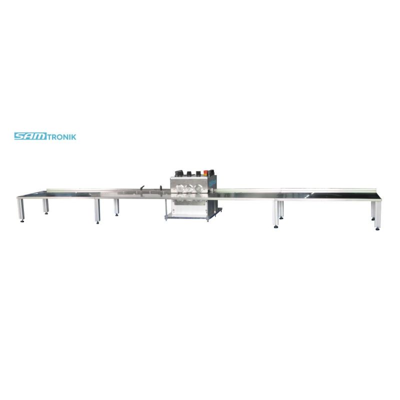
PCB Depaneling machine
Attentionmatters :
*Before using this equipment, please read thismanual carefully, it will make your machine work safely.
* Under no circumstances,To avoid danger shouldnot remove the blade the protective plat .
*This unit is designed only for the board that isseparated by the V-CUT. Do not use it for other purposes.
* When operating the unit, it should not be wornin loose clothing. Long hair should be tied to avoid being caught by themachine.
Main features :
1. The board cutting iscompleted by six blades, and the upper and lower pieces are a group to form acutting unit. They are A.B.C three groups . The whole cutting process isdivided into three stages. The A group of blades cuts the circuit board by 40%first. Then the B group is again crushed from the slot cut by the A group ofblades, and 40% of the cutting amount is completed again. Finally, the C groupcutting the 20% and repairing light, because the amount of cutting is smalleach time, the stress generated during the cutting process is reduced by morethan 80% compared with the traditional one-time cutting method, the edge of thedivided circuit board is smoothly, and the board surface is very flat.Nottwisting and no tilting.
2. Due to the multiplecutting, the cutting process is very smooth, greatly improving the positioningability of the V-CUT slot. Even if the V-CUT slot is very shallow, the V-CUTslot will not jump out from the guiding knife. The situation to avoid bad.
3. Due to the small cuttingforce of the blade, the durability of the blade is greatly improved, and theuse cost is reduced.
Techincal Date
Max PCB Length | No limited | Work temperature | 10—35℃ |
PCB thickness | 0.5--3mm | PCB Material | Aluminum substrate ,Copper board FR1~4,Glass fiber plate |
Feeding pcb speed | 0-500mm/sec,Variable Speed | Machine size | 540mm*280mm*240mm 2400mm*400mm*240mm |
Blade material | Swiss SKH7 HSS | Weight | 45kg |
Power supply | 220V/50HZ | Storage temperature | -20~50℃ |
V-cut groovecomponents width limit:V-CUT groove right side width no limited .Left side width no more than100mm .
Install and Preparation
1. Check the contents of the package, including the following parts:main machine, User manual, power cord, hex wrench for adjustment.
2. Remove the machine packaging film and place it on a flat and sturdyworkbench. It should not be too far from the power outlet.
3. To prevent static damage to the parts on the circuit board, themachine should be grounded reliably. If the ground wire in the power socket isreliable and effective, it should be reliably grounded when the machine ispowered.
4. Wipe off the anti-rust grease on the machine blade.
5. After placing the machine, connect another stainless steel pallet ofthe machine to the main unit. The main unit has a connecting aluminum strip andtighten the four fixing screws. Under normal circumstances, the outer part ofthe supporting blade is 2mm lower than the height of the cutting edge. In orderto avoid the friction between the lower part of the PCB and the pallet when theblade is cut, the resistance is too large and the board is not smooth.
Adjustment and operation
1. First confirm the components on the circuitboard do not touch machine body. Under normal circumstances, the height of thecomponents should not exceed 16mm.
2. After the circuit board is fed into themachine along the baffle, it can be cleanly separated by the blade and thestress during the splitting process is minimized, depending on whether thespacing between the three sets of upper and lower round knives is appropriate.Therefore, the blade pitch should be adjusted according to the thickness andmaterial of the divided circuit board. In order to achieve the best results.
The first set of blades cuts 30-50% of theresidual thickness of the board first, and then the second set of blades isagain milled through the slots cut by the first set of blades, again completing30-40% of the cut, and finally by the third The group of blades cuts the last10-20% of the cut and trims the cuts. When adjusting the blade, first loosenthe blade fixing screw and fix the screw on the inner side of the blade mainboard to screw the blade height adjustment screw to adjust the blade height.Rotate the blade height screw clockwise to raise the height of the upper bladeand counterclockwise to lower the height of the upper blade. Each small grid onthe scale plate has a scale of 0.01mm, a large grid of 0.1mm, the screw isscrewed through the corresponding number of grids, and the blade is floated upand down to the corresponding height. After the adjustment is completed,tighten the holder fixing screw. Then, manually transfer the circuit boardalong the V-groove of the board slowly to the machine. After entering thesecond set of blades, stop the motor, move the guide plate and gently leanagainst the circuit board, so that the guide plate is adjusted on the bestposition.
3. Separating PCBB speed adjustment, after theabove adjustment work is completed, the circuit board can be manually sent intothe machine for testing separate. If separste effect is ideal, the machinepower switch can be turned on, the blade will rotate, and the circuit boardwill be automatically involved. The machine splits, the speed of the machine isadjustable. User could adjust the speed of the board according to work habitsand process requirements. Generally speaking, the V-groove on the board is deepor the operation skill is used to adjust the speed.
4. Replace the blade, loosen the tool holderscrew, adjust the upper knife to completely separate from the lower knife edge,loosen the screw in the knife shaft, and gently tap the screw head tocompletely remove the blade (including the central shaft). Next, remove all theadjustment pads that are placed on the blade shaft, put them on the new blades,and replace them in the reverse order. After the blade is in place, check ifthe tip of the unremoved blade is aligned. If it is not aligned, remove theblade and increase or decrease the number of the spacer until it is alignedwith the tip of the original blade. The blade fixing screw can be used.
Maintenance:
Maintenanceduring the use of the machine is relatively simple, just keep the machineitself clean, and regularly apply anti-rust oil to the upper and lower blades.Special personnel should be assigned to operate and maintain. To ensure theaccuracy of the machine, do not use or store it in places where the temperatureis too high or too low.